LTE FDD
For Waveform Playback (ARB) capability.
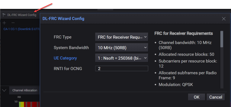
The DL-FRC Wizard Config button is displayed in the toolbar when a Downlink E-UTRA carrier is added. Clicking this button opens the DL-FRC Wizard Config dialog that allows you to configure Downlink E-UTRA carrier with FRC settings.
Information Fields Related to DL-FRC Configuration
Subcarriers per Resource Block
Allocated Subframes per Radio Frame
Maximum Number of HARQ Transmissions
Information Bit Payload for Sub-Frames 1,2,3,4,6,7,8,9
Information Bit Payload for Sub-Frame 5
Information Bit Payload for Sub-Frame 0
Number of Code Blocks per Sub-Frame
Binary Channel Bits per Sub-Frame for Sub-Frames 1,2,3,4,6,7,8,9
Binary Channel Bits per Sub-Frame for Sub-Frame 5
Binary Channel Bits per Sub-Frame for Sub-Frame 0
Max. Throughput averaged over frame
|
SCPI Command |
[:SOURce]:RADio:LTEFdd:WAVeform[:ARB]:CCARrier<n>:DLINk:CONFig:FRC <string> |
|
SCPI Example |
RADio:LTEFdd:WAVeform:CCARrier:DLINk:CONFig:FRC "FrcType:RRECeiver,SystemBandwidth:BW10,UeCategory:CAT1L1,RntiOcng:2" |
|
Notes |
Set only (Immediate Action). The string is a comma-separated list of key:value pairs for all DL FRC wizard settings. |
|
State Saved |
No |
|
Preset |
Refer to the element definition of the data part below. |
|
Range |
Refer to the element definition of the data part below. |
|
Initial S/W Revision |
A.20.01 |
The preset value is same as the default value of each setting definition.
|
Settings |
Symbols in the data part |
Values in the data part |
Preset values |
|
FRC Type |
FrcTypeSetting |
RRECeiver|MILC3to5|MILC1|MILC2|QPSKR13|QAM16R12|QAM64R34|SPRBedge|TAP2|TAP4|FRCFDD |
RRECeiver |
|
System Bandwidth |
SystemBandwidthSetting |
BW1_4|BW3|BW5|BW10|BW15|BW20 |
BW10 |
|
RB Offset |
RbOffset |
0-99 (integer) |
N/A |
|
FRC QPSK R1-3 |
FrcQpskR1_3 |
R2|R4 |
N/A |
|
FRC QAM16 R1-2 |
FrcQam16R1_2 |
R3 |
R3 |
|
FRC QAM64 R3-4 |
FrcQam64R3_4 |
R5|R6|R7|R8|R9 |
N/A |
|
FRC Single PRB |
FrcSinglePrb |
R0|R1T10|R1T20 |
N/A |
|
FRC Two Antenna |
FrcTwoAntenna |
R10|R11|R30 |
N/A |
|
FRC Four Antenna |
FrcFourAntenna |
R12|R13|R14 |
N/A |
|
FRC FDD Sub Type |
FrcFddSubType |
R15|R16|R17 |
N/A |
|
UE Category |
UeCategorySetting |
CAT1L1|CAT2L2|CAT3L2|CAT4L2|CAT5L4|CAT6L2|CAT6L4|CAT7L2|CAT7L4|CAT8L8|CAT9L2|CAT9L4|CAT10L2|CAT10L4|CAT11L2|CAT11L4|...|CAT14L8|...|CAT21L4 |
CAT14L8 |
|
RNTI for OCNG |
RntiOcngSetting |
0–65535 (integer) |
2 |
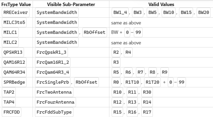
This section describes individual setting parameters of DL FRC configuration.
Sets the FRC type.
The software sets the parameters displayed in the lower section of the window to predetermined values for the selected FRC Type and Reference Channel.
| FRC Type | Reference Channel |
| FRC for Receiver Requirements (FDD) | R.1 FDD at 1.4 / 3 / 5 / 10 / 15 / 20 MHz |
|
FRC for maximum input level for UE category 3-5 |
R.1 FDD (64QAM R=3/4) at 1.4 / 3 / 5 / 10 / 15 / 20 MHz |
|
FRC for maximum input level for UE category 1 |
R.1 FDD (64QAM R=3/4) at 1.4 / 3 / 5 / 10 / 15 / 20 MHz |
|
FRC for maximum input level for UE category 2 |
R.1 FDD (64QAM R=3/4) at 1.4 / 3 / 5 / 10 / 15 / 20 MHz |
|
FRC QPSK R=1/3 |
R.2 FDD (10 MHz), R.4 FDD (1.4 MHz) |
|
FRC 16QAM R=1/2 |
R.3 FDD (10 MHz) |
|
FRC 64QAM R=3/4 |
R.5 FDD (3 MHz), R.6 FDD (5 MHz), R.7 FDD (10 MHz), R.8 FDD (15 MHz), R.9 FDD (20 MHz) |
|
FRC Single PRB (Channel Edge) |
R.0 FDD (1.4 MHz), R.1 FDD (10 MHz), R.1 FDD (20 MHz) |
|
FRC two antenna ports |
R.10 FDD (10 MHz), R.11 FDD (10 MHz), R.30 FDD (20 MHz) |
|
FRC four antenna ports |
R.12 FDD (1.4 MHz), R.13 FDD (10 MHz), R.14 FDD (10 MHz) |
|
FRC FDD |
R.15 FDD (10 MHz), R.16 FDD (1.4 MHz), R.17 FDD (10 MHz) |
Refer TS 36.101 Annex A.
|
SCPI Command |
N/A |
|
Notes |
No SCPI, GUI only |
|
State Saved |
No |
|
Preset |
FRC for Receiver Requirements (FDD) |
|
Range |
FRC for Receiver Requirements (FDD) | FRC for maximum input level for UE category 3-5 | FRC for maximum input level for UE category 1 | FRC for maximum input level for UE category 2 | FRC QPSK R=1/3 | FRC 16QAM R=1/2 | FRC 64QAM R=3/4 | FRC Single PRB (Channel Edge) | FRC two antenna ports | FRC four antenna ports | FRC FDD |
|
Initial S/W Revision |
A.20.01 |
Sets the system bandwidth and number of resource blocks for the fixed reference channel.
The behavior of the System Bandwidth field depends on the selected FRC Type:
When FRC Type is set to FRC for Receiver Requirements (FDD), FRC for maximum input level for UE category 3-5, FRC for maximum input level for UE category 1, or FRC for maximum input level for UE category 2, the System Bandwidth field is active and all six bandwidth options are selectable (1.4 MHz / 3 MHz / 5 MHz / 10 MHz / 15 MHz / 20 MHz). All use R.1 FDD at the selected bandwidth.
When FRC Type is set to FRC QPSK R=1/3, FRC 16QAM R=1/2, FRC 64QAM R=3/4, FRC Single PRB (Channel Edge), FRC two antenna ports, FRC four antenna ports, or FRC FDD, the system bandwidth is determined by the selected reference channel and is fixed. The second field in the dialog shows the reference channel selector for that FRC type instead of System Bandwidth.
|
SCPI Command |
N/A |
|
Notes |
No SCPI, GUI only When the DL FRC config dialog is invoked, the current value of System Bandwidth of carrier is shown initially. |
|
State Saved |
No |
|
Preset |
BW10 |
|
Range |
BW1_4 | BW3 | BW5 | BW10 | BW15 | BW20 |
|
Initial S/W Revision |
A.20.01 |
Sets the QPSK R=1/3 value for the FRC. The software adjusts the corresponding parameter values in the lower section based on your selection.
|
SCPI Command |
N/A |
|
Notes |
No SCPI, GUI only |
|
State Saved |
No |
|
Preset |
R2 |
|
Range |
R2 | R4 |
|
Initial S/W Revision |
A.20.01 |
Sets the 16QAM R=1/2 value for the FRC. The software adjusts corresponding parameter values in the lower section based on your selection.
|
SCPI Command |
N/A |
|
Notes |
No SCPI, GUI only |
|
State Saved |
No |
|
Preset |
R3 |
|
Range |
R3 |
|
Initial S/W Revision |
A.20.01 |
Sets the 64QAM R=3/4 value for the FRC. The software adjusts corresponding parameter values in the lower section based on your selection.
|
SCPI Command |
N/A |
|
Notes |
No SCPI, GUI only |
|
State Saved |
No |
|
Preset |
R5 |
|
Range |
R5 | R6 | R7 | R8 | R9 |
|
Initial S/W Revision |
A.20.01 |
Sets the Single PRB value for the FRC. The software adjusts corresponding parameter values in the lower section based on your selection.
|
SCPI Command |
N/A |
|
Notes |
No SCPI, GUI only |
|
State Saved |
No |
|
Preset |
R0 |
|
Range |
R0 | R1T10 | R1T20 |
|
Initial S/W Revision |
A.20.01 |
Sets the Two Antenna Ports value for the FRC. The software adjusts corresponding parameter values in the lower section based on your selection.
|
SCPI Command |
N/A |
|
Notes |
No SCPI, GUI only |
|
State Saved |
No |
|
Preset |
R10 |
|
Range |
R10 | R11 | R30 |
|
Initial S/W Revision |
A.20.01 |
Sets the Four Antenna Ports for the FRC. The software adjusts corresponding parameter values in the lower section based on your selection.
|
SCPI Command |
N/A |
|
Notes |
No SCPI, GUI only |
|
State Saved |
No |
|
Preset |
R12 |
|
Range |
R12 | R13 | R14 |
|
Initial S/W Revision |
A.20.01 |
Sets the FDD for the FRC. The software adjusts corresponding parameter values in the lower section based on your selection.
|
SCPI Command |
N/A |
|
Notes |
No SCPI, GUI only |
|
State Saved |
No |
|
Preset |
R15 |
|
Range |
R15 | R16 | R17 |
|
Initial S/W Revision |
A.20.01 |
Sets the resource block (RB) offset for the FRC.
|
SCPI Command |
N/A |
|
Notes |
No SCPI, GUI only |
|
State Saved |
No |
|
Preset |
0 |
|
Range |
0 to (number of RBs determined by System Bandwidth) |
|
Initial S/W Revision |
A.20.01 |
Sets the UE category. UE categories for DL-SCH channels are implemented according to the 3GPP standard.
The choices for UE Category are:
1: Nsoft = 250368 (bits), Layer = 1
2: Nsoft = 1237428 (bits), Layer = 2
3: Nsoft = 1237428 (bits), Layer = 2
4: Nsoft = 1827072 (bits), Layer = 2
5: Nsoft = 3667200 (bits), Layer = 4
6: Nsoft = 3654144 (bits), Layer = 2
6: Nsoft = 3654144 (bits), Layer = 4
7: Nsoft = 3654144 (bits), Layer = 2
7: Nsoft = 3654144 (bits), Layer = 4
8: Nsoft = 35982720(bits), Layer = 8
Downlink physical parameter values set by UE Category are as shown in the following table.
|
UE Category |
Maximum number of DL-SCH transport block bits received within a TTI |
Maximum number of bits of a DL-SCH transport block received within a TTI |
Total number of soft channel bits |
Maximum number of supported layers for spatial multiplexing in DL |
|---|---|---|---|---|
|
Category 1 |
10296 |
10296 |
250368 |
1 |
|
Category 2 |
51024 |
51024 |
1237248 |
2 |
|
Category 3 |
102048 |
75376 |
1237248 |
2 |
|
Category 4 |
150752 |
75376 |
1827072 |
2 |
|
Category 5 |
299552 |
149776 |
3667200 |
4 |
|
Category 6 |
301504 |
149776 (4 layers) 75376 (2 layers) |
3654144 |
2 or 4 |
|
Category 7 |
301504 |
149776 (4 layers) 75376 (2 layers) |
3654144 |
2 or 4 |
|
Category 8 |
2998560 |
299856 |
35982720 |
8 |
During the carrier aggregation operation, the DL-SCH processing capability can be shared by the UE with that of MCH received from a serving cell. If the total eNB scheduling for the DL-SCH and an MCH in one serving cell—at a given TTI—is larger than the defined processing capability, then the prioritization between DL-SCH and MCH is left up to the UE's implementation.
|
SCPI Command |
N/A |
|
Notes |
No SCPI, GUI only |
|
State Saved |
No |
|
Preset |
CAT5L4 (5 : Nsoft = 3667200 bits) |
|
Range |
CAT1L1 | CAT2L2 | CAT3L2 | CAT4L2 | CAT5L4 | CAT6L2 | CAT6L4 | CAT7L2 | CAT7L4 | CAT8L8 | CAT9L2 | CAT9L4 | CAT10L2 | CAT10L4 | CAT11L2 | CAT11L4 | ... | CAT14L8 | ... | CAT21L4 |
|
Initial S/W Revision |
A.20.01 |
Sets the Radio Network Temporary Identifier (RNTI) for the OCNG for the selected FRC Type.
Refer to the 3GPP TS 36.211
|
SCPI Command |
N/A |
|
Notes |
No SCPI, GUI only |
|
State Saved |
No |
|
Preset |
2 |
|
Min |
1 |
|
Max |
65535 |
|
Initial S/W Revision |
A.20.01 |
These are read-only fields, displayed to provide you information based on your selected FRC Type. A sample screen with information for the FRC for Receiver Requirements is shown below.
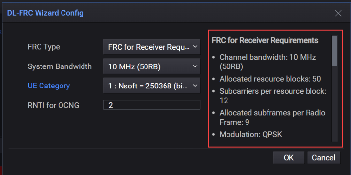
The title of the highlighted information group is changed by the value of your selected FRC Type.
Displays the Channel bandwidth for the selected FRC Type.
|
SCPI Command |
N/A |
|
Notes |
No SCPI, GUI only, Query only |
|
State Saved |
No |
|
Preset |
|
|
Range |
|
|
Initial S/W Revision |
A.20.01 |
Displays the allocated resource blocks for the selected FRC Type and Reference Channel value.
|
SCPI Command |
N/A |
|
Notes |
No SCPI, GUI only, Query only |
|
State Saved |
No |
|
Preset |
|
|
Range |
|
|
Initial S/W Revision |
A.20.01 |
Displays the subcarriers per resource block for the selected FRC Type.
|
SCPI Command |
N/A |
|
Notes |
No SCPI, GUI only |
|
State Saved |
No |
|
Preset |
|
|
Range |
|
|
Initial S/W Revision |
A.20.01 |
Displays the allocated subframes per Radio Frame for the selected FRC Type.
|
SCPI Command |
N/A |
|
Notes |
No SCPI, GUI only |
|
State Saved |
No |
|
Preset |
|
|
Range |
|
|
Initial S/W Revision |
A.20.01 |
Displays the modulation type for the selected FRC Type.
|
SCPI Command |
N/A |
|
Notes |
No SCPI, GUI only |
|
State Saved |
No |
|
Preset |
|
|
Range |
|
|
Initial S/W Revision |
A.20.01 |
Displays the Target Coding Rate for the selected FRC Type.
|
SCPI Command |
N/A |
|
Notes |
No SCPI, GUI only |
|
State Saved |
No |
|
Preset |
|
|
Range |
|
|
Initial S/W Revision |
A.20.01 |
Displays the Number of HARQ Processes for the selected FRC Type.
|
SCPI Command |
N/A |
|
Notes |
No SCPI, GUI only |
|
State Saved |
No |
|
Preset |
|
|
Range |
|
|
Initial S/W Revision |
A.20.01 |
Displays the maximum number of HARQ transmissions for the selected FRC Type.
|
SCPI Command |
N/A |
|
Notes |
No SCPI, GUI only |
|
State Saved |
No |
|
Preset |
|
|
Range |
|
|
Initial S/W Revision |
A.20.01 |
Displays the Information Bit Payload for Sub-Frames 1,2,3,4,6,7,8,9 for the selected FRC Type.
|
SCPI Command |
N/A |
|
Notes |
No SCPI, GUI only |
|
State Saved |
No |
|
Preset |
|
|
Range |
|
|
Initial S/W Revision |
A.20.01 |
Displays the Information Bit Payload for Sub-Frame 5 for the selected FRC Type.
|
SCPI Command |
N/A |
|
Notes |
No SCPI, GUI only |
|
State Saved |
No |
|
Preset |
|
|
Range |
|
|
Initial S/W Revision |
A.20.01 |
Displays the Information Bit Payload for Sub-Frame 0 for the selected FRC Type.
|
SCPI Command |
N/A |
|
Notes |
No SCPI, GUI only |
|
State Saved |
|
|
Preset |
|
|
Range |
|
|
Initial S/W Revision |
A.20.01 |
Displays the Transport block CRC size for the selected FRC Type.
|
SCPI Command |
N/A |
|
Notes |
No SCPI, GUI only |
|
State Saved |
|
|
Preset |
|
|
Range |
|
|
Initial S/W Revision |
A.20.01 |
Displays the Number of Code Blocks per subframe for the selected FRC Type.
|
SCPI Command |
N/A |
|
Notes |
No SCPI, GUI only |
|
State Saved |
|
|
Preset |
|
|
Range |
|
|
Initial S/W Revision |
A.20.01 |
Displays the Binary Channel Bits per Sub-Frame for Sub-Frames 1,2,3,4,6,7,8,9 for the selected FRC Type.
|
SCPI Command |
N/A |
|
Notes |
No SCPI, GUI only |
|
State Saved |
|
|
Preset |
|
|
Range |
|
|
Initial S/W Revision |
A.20.01 |
Displays the Binary Channel Bits per Sub-Frame for Sub-Frame 5 for the selected FRC Type.
|
SCPI Command |
N/A |
|
Notes |
No SCPI, GUI only |
|
State Saved |
|
|
Preset |
|
|
Range |
|
|
Initial S/W Revision |
A.20.01 |
Displays the Binary Channel Bits per Sub-Frame for Sub-Frame 0 for the selected FRC Type.
|
SCPI Command |
N/A |
|
Notes |
No SCPI, GUI only |
|
State Saved |
|
|
Preset |
|
|
Range |
|
|
Initial S/W Revision |
A.20.01 |
Displays the maximum Throughput averaged over 1 frame for the selected FRC Type.
|
SCPI Command |
N/A |
|
Notes |
No SCPI, GUI only |
|
State Saved |
|
|
Preset |
|
|
Range |
|
|
Initial S/W Revision |
A.20.01 |